Liên hệ quảng cáo
Analysis of FRP-strengthened short RC columns by analytical and numerical approaches
Short reinforced concrete (RC) columns strengthened in shear using carbon or glass fiber-reinforced polymers (CFRPs or GFRPs) with different configurations (partially or fully strengthened along the height) are analyzed using analytical and numerical approaches.s
|
Dr. Le Nguyen Khuong Ms. Ngo Thi Hong Que Ms. Nguyen Manh Ha University of Transport Technology Dr. Nguyen Trung Kien Dr. Vu Hoai Nam |
ABSTRACT: Short reinforced concrete (RC) columns strengthened in shear using carbon or glass fiber-reinforced polymers (CFRPs or GFRPs) with different configurations (partially or fully strengthened along the height) are analyzed using analytical and numerical approaches. First, the author combines the design equations proposed in construction guidelines of Europe and Japan for reproducing the concrete confinement provided by FRP wraps and the strength assessment of each column. Then, numerical pushover analyses will be performed by finite element method with the INSA concrete model. Both approaches are successful in predicting the strength of the short FRP-retrofitted RC columns. For all the short FRP-strengthened columns, very consistent cracking patterns and the observed failure modes have been predicted by numerical approach.
Keywords: fiber reinforced polymer retrofit, short rc column, nonlinear pushover procedure.
1. INTRODUCTION
Short reinforced columns (RC) in buildings and bridges designed according to older codes may experience dangerous brittle shear failure as exhibited by damage reconnaissance projects from past earthquakes, which is mainly due to their shear deficiencies (widely spaced and/or poorly closed stirrups). Colomb et al. [1], [2] investigated the effectiveness of different retrofitting configurations for short square RC columns with the same aspect ratio of 3 by considering full and partial FRP strengthening along the height of the columns and by using two different FRP materials: carbon FRP (CFRP) and glass FRP (GFRP). The FRP retrofitting changed the failure mode of the short RC columns from a brittle shear failure for the as-built column to a more ductile failure.
In this paper, the analytical approach proposed by Xiao et al. [3] is employed to assess the strength of the as-built and FRP retrofitted columns. The failure mode is deduced from a comparison between the flexural shear obtained from the designed ultimate flexural capacity under the double curvature condition of the tests and the shear strength calculated from the lines of Priestley. Instead of using the analogy of the confinement effect provided by a conventional transverse reinforcement, the contribution of the FRP wrapping to the global shear strength of the retrofitted columns is assessed using design equations from the French recommendation guide [4].
In addition to the analytical approach based on design relationships, it is of interest to assess the effectiveness of the numerical approach in predicting the strength, failure mode and ductility of FRP-retrofitted specimens. Here, the smeared-fixed crack approach adopted in a previous paper for CFRP-retrofitted RC walls with different aspect ratios is used.
2. EXPERIMENTAL DATABASE
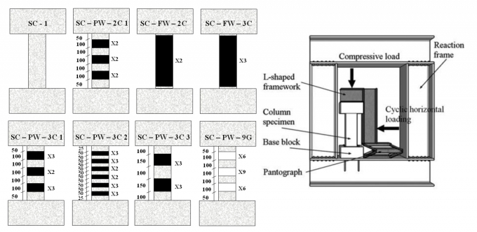
The experimental program under consideration has already been presented in previous works by Colomb et al [1]. The experimental program included RC columns with 200 x 200mm square cross section, corresponding to 2/3 of the size of short columns used in buildings. The aspect ratio H/L of the investigated columns was set to 3, corresponding to the upper limit of aspect ratios for short columns, and was tested under the double curvature condition. A constant axial load of 126kN was applied to the columns, on the basis of a nominal design axial load ratio of 0,1. The steels are consistent with the current standard, with a guaranteed yield strength equal to 500MPa (steel type S500B). The compression strength at 28 days was evaluated at 31,5MPa with an uncertainty of 1,5MPa. The columns were reinforced at their ends using two large reinforced concrete blocks with dimensions of 600 x 600 x 300mm to provide the strong stiffness required by the double curvature test (fixed-fixed boundary conditions in rotation). Two FRP composites were investigated for retrofitting the square columns: CFRPs and GFRPs. The mechanical parameters for one layer of CFRP and for GFRP strips with a thickness of 1 mm are summarized in Table 1. The investigated FRP-retrofitted configurations are displayed in Fig. 2.1:
Table 2.1. CFRP and GFRP material properties
 |
 |
| Fig. 2.1: Setup of the test [1] |
The FRP retrofitting noticeably improves the behavior of the as-built column: From a fragile failure experienced by this reference column with an almost elastic behavior up to the ultimate load, the FRP retrofitting allows a more ductile failure with a clear enhancement of both the global strength and the ductility. The fully height-retrofitted columns experience bending failure modes, whereas the partially retrofitted columns exhibit shear failure modes.
3. ANALYTICAL APPROACH
The FRP wrapping provides an additional confinement for the deficient RC columns, representing a very attractive solution due to their lightweight, high strength and excellent corrosion resisting capabilities. In accordance with the French regulatory guide [4], the confined strength is evaluated as a function of the unconfined strength and the FRP geometric and material characteristics as follows:
(1)
in which f’cc is the confined compressive strength, yf is a coefficient parameter equal to 0.6 for a square section rounded at the edge, k1 is an efficiency coefficient that depends on the value of the unconfined compressive strength, kc and kh are geometric parameters (in the cross section and along the height of the column).
The confinement pressure fpu,k in Eq. depends on the equivalent confinement stiffness Ep and the FRP characteristics as follows:
 |
(2)
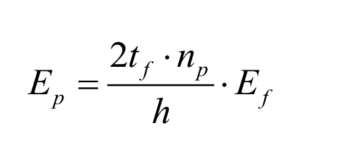
where efu,k denotes the threshold strain value in the FRP composite from which the concrete shear strength deterioration due to diagonal cracking is observed. Priestley et al. [11] recommended the value of 0,004, which was subsequently chosen for all the investigated columns. The equivalent confinement stiffness Ep of the FRP wrapping for a rectangular square section is calculated as:
 |
(3)
where Ef is the elasticity modulus of the composite, tf is the nominal thickness of the reinforcement, np is the number of composite layers and h is the depth of the section.
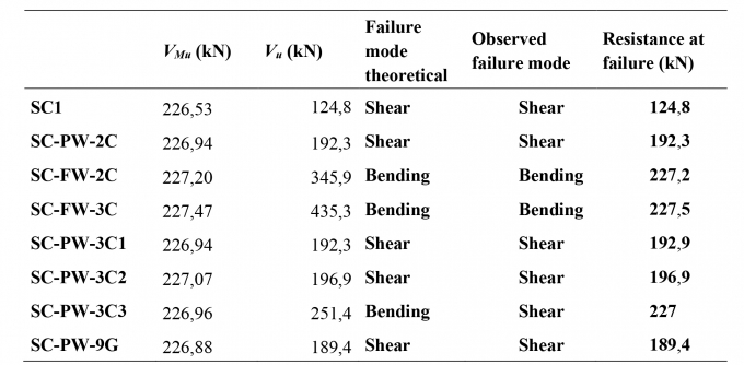
Then, the ultimate flexural capacity Mu is assessed in accordance with the Japanese guidelines [12] to obtain the flexural shear strength of the FRP-retrofitted columns. The ultimate shear strength of each column is proposed by Priestley et al. [11], decomposing the global shear strength into several contributions from the concrete, axial load, transverse reinforcement and FRP-wrapping of the section. The failure mode and the ultimate strength of the FRP-retrofitted columns predicted by the analytical approach will be obtained by comparing the flexural shear with the shear strength. The consistency between the predicted failure modes and those observed in the tests are verified.
Table 3.1. The resistance at failure from the ultimate flexural capacity and shear strength
 |
The analytical approach successfully provides reliable resistance values as well as failure modes, with the exception of the SC-PW-3C3 case. It has to be noted that no predicted values of ductility are provided by this approach. On the contrary, the following approach based on the Finite Element Method under the plane stress assumption aims at providing predictions of the global strength, failure mode and ductility.
4. NUMERICAL APPROACH BY FINITE ELEMENT PUSHOVER ANALYSIS
This section is devoted to the brief presentation of the concrete model and the steel model used in the pushover analysis for the short FRP-retrofitted RC columns. The concrete model, available in the finite element code CAST3M [7], is based on the classical smeared fixed crack assumption [8], [9]. The model follows a local approach and the mesh dependency on the softening regime in traction is addressed through the fracture energy approach introduced by Hillerborg et al. [10] and employed by Bažant and Oh[11]. This approach has also been validated for predicting the behavior of CFRP-retrofitted shear walls with different aspect ratios [12].
In addition to the bar elements modeling the FRP bands, the concrete confinement effect provided by the FRP-strengthening has to be reproduced. In this 2D analysis under the plane stress assumption, the confinement effect is considered by changing the material properties of the concrete area where the FRP strips are bonded. For each confined area, the modified material properties are given based on the analytical formulas previously presented: the confined compressive strength f’cc is assessed using Eq. which is given in the French regulatory guide, the tensile strength f’t is taken as the compressive value divided by 10.
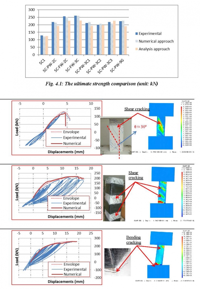
Next, the pushover curves obtained from the numerical approach are compared to the experimental data along with the numerically predicted failure modes versus the failure modes observed during the tests. To compare to the numerical pushover analysis, the experimental curve is derived from the experimental data by plotting the envelope of the hysteresis loops.
In terms of strength, the experimental, analytical and numerical results are compared in Fig. 4.1 for all the columns. It can be observed that the numerical predictions are very accurate in terms of the strength in comparison with the experimental results and are more accurate than the analytical predictions. In addition, all the failure modes observed during the double curvature tests are well predicted by the numerical approach. Fig. 4.2 presents the pushover curves and failure modes of the columns SC1, SC-PW-3C1 and SC-FW-3C.
 |
| Fig. 4.2: Pushover curves and failure modes of the columns SC1; SC-PW-3C1; SC-FW-3C |
5. CONCLUSION
An experimental program including an as-built short RC column with dimensions 200 x 200 x 600mm and seven FRP-strengthened columns using different configurations and FRP materials (CFRP and GFRP) has been re-analyzed using both analytical and numerical procedures. The study compared the efficiency of both approaches for predicting the strength, failure mode and ductility for all the FRP-retrofitted configurations.
Both approaches are successful in predicting the strength of the short FRP-retrofitted RC columns, with a better accuracy provided by the numerical approach. For all the short FRP-strengthened columns, very consistent cracking patterns and the observed failure modes have been predicted. Finally, in contrast to the analytical approach, our numerical strategy enables valuable ductility results to be obtained. As observed in the experimental program, the strengthening using several CFRP strips is found to be more advantageous than a complete wrapping along the height or a partial wrapping using a few large strips, in that this optimized configuration leads to an enhancement of the global ductility without altering the global strength of the FRP-retrofitted column to a significant extent. As a result, the proposed approaches are relevant and efficient for investigating different FRP-strengthened configurations for short RC columns. Because the proposed model is only based on limited experimental data, there is an obvious need for further experimental investigations to further validate the proposed analytical and numerical approaches.
References
[1]. F. Colomb, H. Tobbi, E. Ferrier, and P. Hamelin (2008), Seismic retrofit of reinforced concrete short columns by CFRP materials, Composite Structures,vol. 82, no. 4, pp. 475-487.
[2]. G. Promis and E. Ferrier (Jan. 2012), Performance indices to assess the efficiency of external FRP retrofitting of reinforced concrete short columns for seismic strengthening, Construction and Building Materials, vol. 26, no. 1, pp. 32-40.
[3]. Y. Xiao, H. Wu, and G. Martin (1999), Prefabricated Composite Jacketing of RC Columns for Enhanced Shear Strength, Journal of Structural Engineering, vol. 125, no. 3, pp. 255-264.
[4]. AFGC (2011), Réparation et renforcement des structures en béton au moyen des matériaux composites: Recommandations provisoire, Association Frainçaise de Génie Civil.
[5]. JPDPA (1999, Seismic Retrofitting Design and Construction Guidelines for Existing Reinforced Concrete (RC) and Steel-encased Reinforced Concrete (SRC) Buildings with FRP Materials, Japan Building Disaster Prevention Association. in Japanese.
[6]. M. J. N. Priestley, R. Verma and Y. Xiao (Aug. 1994), Seismic Shear Strength of Reinforced Concrete Columns, Journal of Structural Engineering, vol. 120, no. 8, pp. 2310-2329.
[7]. E. Le Fichoux (2011), Présentation Et Utilisation De Cast3m, Support of CEA (http://www-cast3m.cea.fr).
[8]. N. Ile and J. Reynouard (2000), Nonlinear analysis of reinforced concrete shear wall under Earthquake loading, Journal of Earthquake Engineering, vol. 4, no. 2, pp. 183-213.
[9]. O. Merabet and J. Reynouard (1999), Formulatin d’un modèle élasto-plastique fissurable pour le béton sous chargements cycliques, Contrat EDF/DER, Rapport Final, URGC-Structures.
[10]. A. Hillerborg, M. Modéer, and P.-E. Petersson (Nov. 1976), Analysis of crack formation and crack growth in concrete by means of fracture mechanics and finite elements, Cement and Concrete Research, vol. 6, no. 6, pp. 773-781.
[11]. Z. P. Bažant and B. H. Oh (1983), Crack band theory for fracture of concrete, Matériaux et Construction, vol. 16, no. 3, pp. 155-177.
[12]. K. Le Nguyen, M. Brun, A. Limam, E. Ferrier, and L. Michel (2014), Pushover experiment and numerical analyses on CFRP-retrofit concrete shear walls with different aspect ratios, Composite Structures, vol. Volume 113, pp. 403-418.
Tag:


Bình luận
Thông báo
Bạn đã gửi thành công.